Research: Tillable images and cloth shading
- Michael Cauchi
- Jan 23, 2017
- 13 min read
Hey! Ok, so this paper was made for a university assignment. Figured it would be worth posting to share the time and effort for anyone who wants to look more into cloth shading :) Hope this helps out! The original research paper as well as any image files can be downloaded here: https://drive.google.com/drive/folders/0B5p0Bnw0GH9ZeEhqTHh0VWhkNzg?usp=sharing
Tillable images and cloth shading

Abstract Creating realistic cloth for animation or VFX can be tricky and there are often many trade-offs between quality and time spent to producing convincing shaders. In this paper we create tillable maps that are intentionally made to add as much control as possible without forcing a complicated workflow. We also discuss key contributing factors for cloth shading and using fractals to add a more natural feel to the materials. This is in order to speed up the cloth shading process for less technical artists.
1. Introduction When creating digital character many artists experience some difficulty creating a convincing clothing and much of this is due to the unique shading properties of cloth which do not match that of many real world BRDF’s (or bidirectional reflectance distribution function ) . There is also a great variety of fabric weaves which drastically impacts a cloths physical and visual properties. In this paper I will be focusing on creating an easy to use method of creating as many different “looks” with use of a pre generated image library which can be combined to imitate various types of cloth with wear or not. The reason I am proposing this method is due to the ease of production and relatively high quality to development time ratio. However, this method is by no means a replacement for the existing methods but I feel it does fill a difficulty/time gap. We may also be able to answer the question “How many texture-based assets can be reused between different materials?” Another important consideration to make for this paper was the physically shape of our final shaders in the results, however, the physically simulation of a cloth is important to the shading information for a still frame (Aliaga et al. 2015)

Figure 1: graph showing where I believe this method will fit
2. Related work On the subject of cloth shading and modelling there has been a long history of research. Most recent research papers have a heavy focus on micro cylinder visualization to capture geometry that replicated the complex interplay of fabric fibers all the way down to a sub yarn level (YUKSEL et al. 2012, SADEGHI et al. 2013 and ZHAO et al. 2016) This creates the most realistic cloth visualisations of any method that is currently in use. While others focus much more on the effects of the fibrous nature of cloth and how that effects its key shading concepts like the heavily pronounced Fresnel effect (Khungurn et al. 2015) Other research papers focus on the relationship between shape/simulation of cloth and how that effects how the cloth is perceived and then repeats this with shaders to see if that has a smaller or greater effect on how the cloth is received (Aliaga et al. 2015) 3. Modelling EDIT: since publishing this paper for my university assignment I have found out about a open source software called "texGen" for modelling thew weaves which can be found here: http://texgen.sourceforge.net/index.php/Main_Page Give it a look! 3.1 Fabric weave types The first stage in the creation of my tillable images was to pick out key weave types that allow for me to cover the largest range of clothing with the least amount of images. A key point to take note
of is how weaving is done and to get realistic results both the warp and weft of the fabric must reflect its real world usage. Warp: The warp yarn is pulled tight through the weaving apparatus and this has very little vertical/horizontal variation of position. This should be reflected in any maps I generate. Weft: The weft yarn is the part of the fabric which is actually weaved over and under the warp yarn. Information on how to weave a fabric is often shown in grid like diagrams consisting of black and white squares. A white square represents the weft yarn being pulled over the warp whereas a black square shows where the weft is under the warp yarn.

Figure 2: Common fabric weave patterns
In clothing the most common weaves are the plain, twill and satin weaves. There are many other much more complex weave patterns (Such as herringbone) however a majority of shading can be done with variations of the three weaves mentioned before. Why is this important: Fabric weaves do not only dictate the physical properties such a rigidity and stretch but they also contribute heavily to the visible properties of the cloth such as anisotropy with satins having the most anisotropy of any fabric type and plain weaves having the least.
3.2 Grid method As I wish to make tillable maps it is important that the weaves I model can be tiled evenly in both the U and V co-ordinates. Many weaves were able to be built on a 10x10 grid (with an 11th row and column added for tile-ability). In order to preserve volume of the yarns it was much easier to start off using a grid of nurbs curves and an image plane behind with the black and white weave pattern. The nurbs curves could then be converted to geometry so that the strands have consistent volume throughout which will help prevent having any seams once the image is tiled.

Figure 3: modelling process
1) Place flat grid of curves with exactly one unit between each curve 2) Add height variation on each curve to match the weaving pattern 3) Convert nurbs to tube mesh 4) Assign surface shaders to warp and weft for ID maps 5) Final image output
3.3 shaderball In order to test any shaders I wrapped a shaderball in fabric using marvelous designer in order to have correct primary forms and UVs to help demonstrate the shaders on a more appropriate model. It is especially important that primary forms like folds are captured in geometry and not the shader to have more accurate simulations. There are three primary regions for the cloth with each of which being made to demonstrate how the shader reacts under different simulated states. The top third is both stretched and tightly folded as you travel down to show transitions. The middle third is sown to show similar pipe folds to clothing and the bottom is stretched out which helps show anisotropy satin materials. (Aliaga et al. 2015)
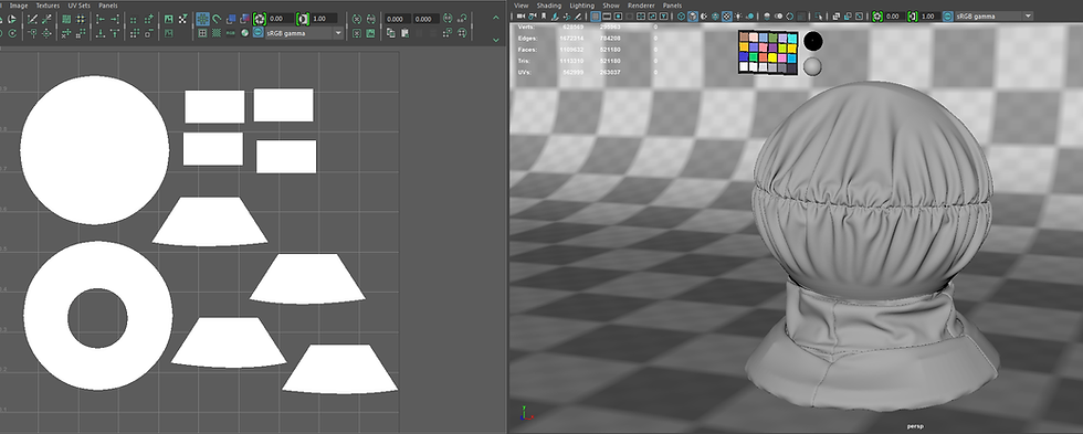
Figure 4: Mesh created for shading tests by wrapping cloth around a shaderball
3.4 Geometry from reference imagery Using as much information as possible directly from real world imagery is highly beneficial so in order to do this I created a node script using the Foundrys’ Nuke which generates height information from input imagery. This was done by creating several high pass filters using blur and minus operations to isolate details or larger forms on the surface and then adds them back together, this give the user control over the amount that each frequency of detail is blended into the final displacement map. The script has its limitations, although it does well at removing lighting information the quality of the final image output is still determined by the quality of the lighting. For the most accurate results from this script the lighting should be coming from the direction of the camera. Due to this the script is most helpful for smaller details rather than large creases and other similar forms. (Cauchi, 2016) (Note: This nuke script was originally made by myself for use in the masterclass assignment.)

Figure 5: image to displacement graph
4. Rendering Once the fabric weaves were modeled the information had to be extracted via rendering. This was done using vray 3.4 with maya however any render will allow for the same process to be used. The geometry was shaded using the Maya surface shader. 4.1 Camera focal length The focal length of the camera played a substantial role is the end result of these maps. Since they are going to be tiled in an objects UV space the images must show minimal distortion from perspective. Interestingly I found that creating an orthographic camera and rendering with that disabled depth passes within Vray so to compensate for this I experimented with camera focal lengths to help reduce the image depth while maintaining the information contains within the depth pass. I tested 3 different focal lengths which changed size by factors of 10 (50 mm, 500 mm, 5000 mm.)

Figure 6: How the camera focal length effects image distortion
4.2 Passes From the rendering process only 3 primary passes needed since many of the shader properties will not need per fiber information for many of the effects we will need to create for character garments. ID: The ID pass is simply the RGB component. Separate surface shaders were used for the warp and weft of the fabric which will later allow me to add colour variation based on weave direction. This is good for fabrics such as denim which is typically dyed before the weaving process. This produces different colour in both directions. ALPHA: The alpha map will be used to add transparency effects for the cloth. For ease of use this should be combined sparingly due to the moiré effect at mid to high resolution renders. DEPTH: The depth pass will be used for the first layer of displacement, this will add the finest level of form and will also contribute to effects such as anisotropy which is caused by having fine parallel groves in a surface.
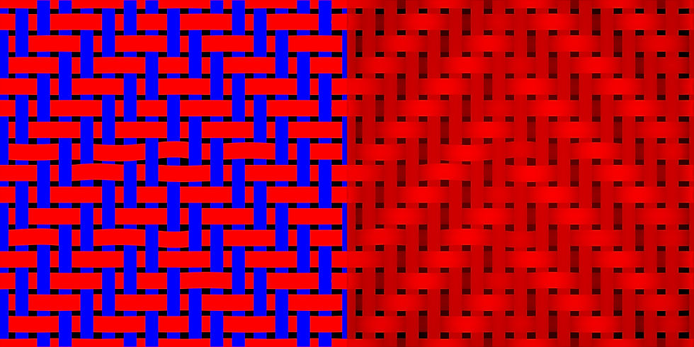
Figure 7: primary render passes (Herringbone weave). Left: ID/RGB pass. Right: Depth/Displacement
4.3 Channel packing After all the images are generated for each weave pattern they were combined into a single image so that they are easier to implement into the shader. The red channel is an ID pass for the warp of the fabric, the blue channel is an ID pass for the weft of the fabric. The green channel is the displacement/bump information and the alpha of the image can be reconstructed by combining the red and blue channels with a simple plus operation.

Figure 8: Final tillable herringbone image. Red and blue channels are the ID map and the green channel is displacement. Alpha can be rebuilt by combining red and blue channels
5. Shading 5.1 BRDF explorer (MERL 100) Before producing my shader I used BRDF explorer with the MERL 100 library to get calibrated values for my reflection attribute at different angles of light. (Burley and Walt Disney animation studios 2012)
5.2 Fresnel/Microfibers The most striking element of cloth shading is the powerful Fresnel effect. In cloth, the Fresnel effect is highly visible due to the microfiber light transmission, due to this many standard materials actually do not produce a high enough reflectance value at glancing angles. This effect can be produced manually in a single shader in Maya by plugging the “facing ratio” function of the sampler into node into the UV coordinates of a ramp, setting the ramps value to greater than one and plugging this into the reflection colour. This is not physically correct however It does produce a more realistic looking cloth shader without having to actually simulate stray fibers along the surface. What is Fresnel: Fresnel is a property of reflection which shows the relationship between the angle of light hitting the surface and glossiness of the resulting reflection. More shallow angle = glossier reflection Steeper angle = More energy absorbed (He, Torrance, Sillion and Greenberg 1991, pp.175-186)

Figure 9: Fresnel effect shown on chrome spheres
5.3 Anisotropy Anisotropy is shown in more sparse weaves like satins. This is because anisotropy is cause by having small parallel/uninterrupted grooves in a surface, this results in reflections being stretched and reduced glossiness of reflections. The reason anisotropy is not shown in other weave types is due to the frequency of interruptions of the grooves between yarns being caused by the weft. What is anisotropy?

Figure 10: Anisotrophy shown on a chrome sphere by tiling a vertical ramp on the UVs
5.4 Transparency Transparency is an incredibly important to capturing realistic thin fabrics like which you would see with plain sheer curtains, typically though, transparency is only visible in in fabrics which have thinner single ply yarns in their weave. Due to this transparency is not needed for many cloth types and is very rarely seen in clothing. To create convincing transparency I used the alpha maps generated in the earlier modelling/rendering stages so that the transparency matches the weave rather than being uniform.
5.5 Bump VS Displacement There are two methods to adding depth information into a shader, for cloth this is highly important to get an organic feeling material since cloth is never perfectly flat due to structural imperfections in the weave caused by the weft yarns. I found a combination of both methods gives me the best quality/speed ratio (Secondary forms and bump for tertiary details)
5.5.1 Bump The first of the two methods for adding depth is the bump channel located in most standard materials. Bump simulates changes in the geometries without actually effecting the geometry its self. This cause bump to be a much faster process in rendering however bump is very limited in what size of forms it can do. (tertiary details like threads are the maximum bump can accurately simulate) 5.5.2 Displacement Displacement is the second method for adding depth to a material and can typically be added via the shading group of a material. Since displacement relies on creating new geometry at render time it is a very heavy to calculate and should only be used for secondary forms in order to minimalize the amount that the model has to be subdivided 5.6 Fractals The final aspect to creating realistic cloth displacement is the use of secondary forms, these can be generated manually with tillable maps however it is much quicker to combine multiple fractals using the maths nodes. Using one fractal on its own gives a very predictable CG look but when several fractals with different scales are combined with multiply or plus operations it breaks up the CG look into a surface with a more realistic feel.
5.6.1 Hierarchy of form As mentioned earlier in the displacement and fractal sections a very important factor of realism is what I refer to as the “hierarchy of form”, by this I mean that there are several levels of detail. Primary which involves folds and major silhouette defining features, this should always be done in geometry if your polygon budget allows. Secondary forms which involve tight creases and bumps on the surface, this is best done in a displacement map due to its typically tillable nature. Finally there is tertiary details which for cloth I consider to be the weave of the fabric, this should be done in bump to avoid overly long calculation times before every render.
5.7 Using ID maps To add final details and variations to the cloth we can use the warp/weft ID map generated for each weave at the earlier rendering stage. The ID map contains two values of pure red and pure blue (255,0,0 and 0,0,255), these clean values allow us to easy create masks that drive features such as uv rotation. Other than per thread colour variation in my shader I also use these masks to procedurally generate a bump map for fibre details. This was done by creating a vertical ramp and adding a tiling of 12 however this creates a problem. If the user wishes to change the size of the fabric weave than this detail bump map quickly becomes the wrong scale. To get around this I used the UV tiling values from the fabric weave and multiplied its value by 12, this was then plugged into the tiling value of the detail bump map to ensure that it stays the correct relative scale to the fabric weave.
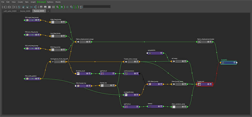
Figure 11: Final shader, all attributes are either fully procedural or are driven by the weave ID/Displacement map
6. Fur
In section 5.2 I spoke briefly about the effect that stray microfibers from the weave has on the Fresnel effect and also mentioned how you can fake this effect by inputting reflection values higher than one. However, for more realistic results it is much better to keep shader values below one in order to remain physically plausible. For fur creation I used a mix of vray fur (Chaos groups’ vray 3.4, 2016) and Yeti (Peregrine labs’ yeti 2.1, 2016), Vray fur was used whenever the fur shown little to no clumping properties, this works fine for 90% of the cloth references I used however in fabrics like coral fleece a more robust grooming solution was required, in these instances Yeti was used. Important factors in creating convincing stray fibres in the density, length and directional variation, since the stray from the primary weave the direction is typically heavily influence by the direction of the weave and this is important to capture.
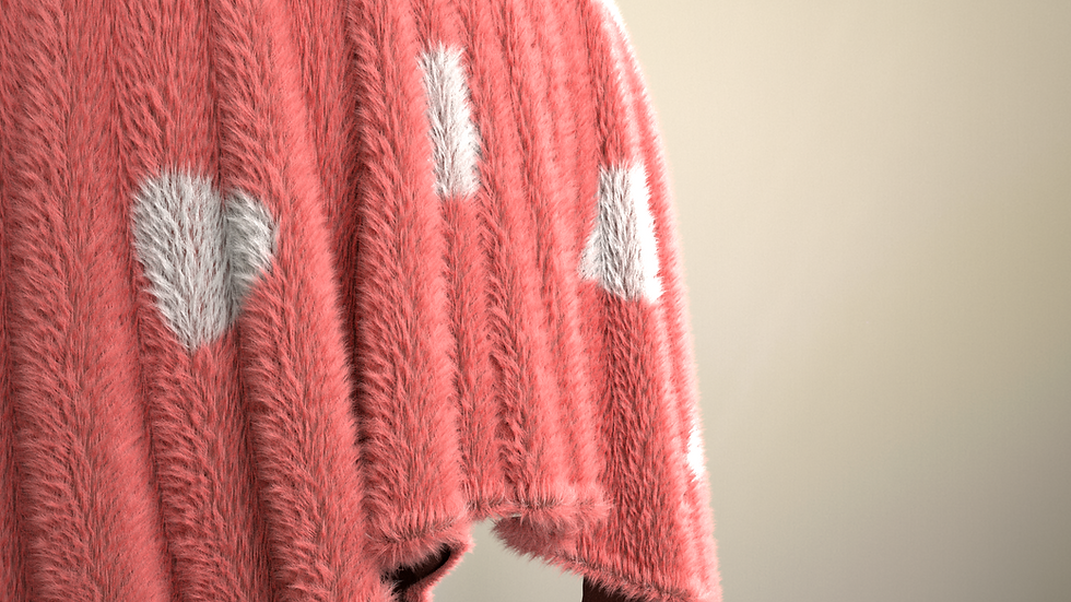
Figure 12: Some fabrics require heavy use of fur simulation. This was groomed using yeti based on Corel Fleece
7. Results

Figure 13: 9 variations created using the technique described by this paper. Total time creating these shaders was 2 hours of work time (plus rendertime)
8. Conclusion In conclusion to this paper I feel the overall results worked well however the time requirement to build the initial library of texture map is too long, due to this my method only becomes beneficial to teams of people working on multiple projects. However, spending more time creating a library of cloth textures will make the shading process much faster and will overall benefit anyone trying to use this method. If more time was to be spent developing this project it would be worth investigating more methods that use information captured directly from images rather than having to hand model the weave patterns.
Project videos
References
Aliaga, C., O'Sullivan, C., Guitierrez, D., Tamstorf, R., Walt Disney Animation Studios, Universidad de Zaragoza, and Disney Research Los Angeles, 2015. Sackcloth or Silk? The Impact of Appearance vs Dynamics on the Perception of Animated Cloth. Burley, B. and Walt Disney animation studios, 2012. Physically-Based Shading at Disney. [online] Available from: https://disney-animation.s3.amazonaws.com/library/s2012_pbs_disney_brdf_notes_v2.pdf
He, X., Torrance, K., Sillion, F. and Greenberg, D., 1991. A comprehensive physical model for light reflection. ACM SIGGRAPH Computer Graphics, 25 (4), 175-186. Cauchi, M, 2016. Nuke displacement Generator Khungurn, P., Schroeder, D., Zhao, S., Bala, K. and Marschner, S., 2015. Matching Real Fabrics with Micro-Appearance Models. ACM Transactions on Graphics, 35 (1), 1-26. Anon, 2016. MarvelousDesigner. CLO Virtual Fashion Inc. Anon, 2016. Maya. Autodesk. Anon, 2016. Nuke. Foundry. Sadeghi, I., Bisker, O., de Deken, J. and Jensen, H., 2013. A practical microcylinder appearance model for cloth rendering. ACM Transactions on Graphics, 32 (2), 1-12. Hoffman, N., 2016. SIGGRAPH University - Introduction to "Physically Based Shading in Theory and Practice". [video] Available from: https://www.youtube.com/watch?v=j-A0mwsJRmk [Accessed 14 Jan. 2017]. Vlado, 2016. Vray. Chaos group. Anon, 2016. Yeti. Peregrine labs. Yuksel, C., Kaldor, J., James, D. and Marschner, S., 2012. Stitch meshes for modeling knitted clothing with yarn-level detail. ACM Transactions on Graphics, 31 (4), 1-12. Zhao, S., Hasan, M., Ramamoorthi, R. and Bala, K., 2013. Modular Flux Transfer: Efficient Rendering of High-Resolution Volumes with Repeated Structures. [online] Available from: http://www.cs.cornell.edu/projects/ctcloth/download/mft13/mft-sg13.pdf Zhao, S., Jakob, W., Marschner, S. and Bala, K., 2012. Structure-aware synthesis for predictive woven fabric appearance. ACM Transactions on Graphics, 31 (4), 1-10. Zhao, S., Jakob, W., Marschner, S. and Bala, K., 2011. Building volumetric appearance models of fabric using micro CT imaging. ACM Transactions on Graphics, 30 (4), 1. Zhao, S., Luan, F. and Bala, K., 2016. Fitting procedural yarn models for realistic cloth rendering. ACM Transactions on Graphics, 35 (4), 1-11.